Heavy Equipment

Komatsu JPB7500V Hydraulic Breaker Assembly/Disassembly Manual

at Heavy Equipment

Free Download Manual: Komatsu JPB7500V Hydraulic Breaker Assembly and Disassembly – Components in PDF and Full.

Komatsu JPB7500V Hydraulic Breaker Manual

Full Manual – Learning

KOMATSU JPB7500V HYDRAULIC BREAKER

ASSEMBLY AND DISASSEMBLY

Forward, Operating Weight, Dimensions in Millimeters, Suspension, Accumulator, Swivels, Threaded Plug, Spring, Slide, Half Clamp, Threaded Plug, Back Head, Back Head, Tight Seal, Distribution, Distribution Box, Distributor, Complete Plunger, Overpressure Valve, Regulation, Strike Regulator Slide, Lubrication, Cylinder, Pin, Piston Seal, Thrust Piston, Spacer, Spacer, Front Guide, Elastic Pin, Assembling, Assembling Bolt, Cradle, Standard Cradle, Cradle Including, Absorber, Soundproofing, Scraper Seal, Plastic Plug, Shock Absorber, Tools, Moil Point, Chisel, Blunt Tool, Accessories, Nylon Ring, Tight Seal, Piston Seal, Excavator Side, Transformation Kit, Knee Piece Axle, Accumulator HP, Accumulator Including, Inflation Screw, Diaphragm, Assembly, Disassembly, Remove the Breaker From Its Cradle, Loosen the Stroke Regulator Plugs, Loosen and Remove the Side Rods, Remove the Back Head, Remove the Distributor, Place the Complete Support, Mount the Lifting Tool, Parts Inspection, Back Head, Check All Helicoid Threads, Check O-ring Seat, Make Sure That the Snap Ring, Make Sure That the Spool Sleeve, Make Sure That Side Rod Seat, Accumulator Seat, Cylinder Seat, Distribution, Piston and Cylinder, Check the Length, Make Sure That the Spacer Seat, Carefully Clean All Parts After Polishing, Spacer, Front Guide, Make Sure That Nut Seats, Suspension, Cradle, Check Shock Absorbers, Make Sure That the Wearing Plates, Repairing, Part Accumulators, Loosen the Inflation Screw, Loosen and Remove the Assembling Screws, Clean the Upper and Lower Accumulator Flanges, Clean Diaphragm Groove, Install New Diaphragm, Mount New Fixing Bolts, Accumulator Inflation, Fully Tighten Setting Screw, Turn the Drain Cock, Untighten Key, After the Pressure Is Stabilized, Remove the Inflating Tool, Front Guide, Front Bushing Replacement, Extraction, Remove the Extractor, Mount the Scraper Seal Ring, Remove the Nut, Upper Bushing Replacement, Mounting, Shank Stop, Extraction, Mounting, Cradle, Welded Beam Repairs, Cradle Welding Procedure, Front Shield, Shield Welding Procedure, Mounting of Wearing Plates, Mind the Orientation, Mount the Tight Rings on the Back, Mount the O-ring, Mount the Distributor, Mount the Accumulator, Mount the Swivel, Mount the Breaker in Its Cradle, Mount the Fixing Cap, Accumulator Nitrogen, Accumulator Inflation, Bushing Hydraulic Extractor, Shank Thrust Wear Gauge, The Pit Is the Same for All Models of Breaker, Piston de Frappe, Strike Piston, Long Term Storage, Wash the Breaker, Remove the Tool, Clean and Dry the Inside of the Front Guide, Cover the Breaker With a Protection Cover, Breaker Pressurization…

  • Pages: 59
  • Size: 2.38 MB
  • Format: PDF (Adobe Reader)

View Manual

MANUAL – KOMATSU – HYDRAULIC – BREAKER – ASSEMBLY – DISASSEMBLY – DIMENSIONS – PARTS – ACCESORIES – INSPECTIONS – ASSEMBLING

FREE MANUAL FOR PROFESSIONALS IN KOMATSU HYDRAULIC BREAKERS – LEARNING
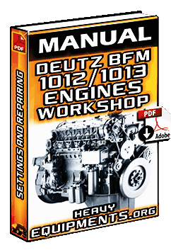
Deutz BFM1012 and BFM1013 Engines Workshop Manual

at Heavy Equipment

Free Download Workshop Manual for Deutz BFM1012/1013 Engines – Specs, Repairing, Disassembly and Tools in PDF/Full.

Deutz BFM1012 and BFM1013 Engines Manual

Full Manual – Learning

DEUTZ BFM1012/1013 ENGINES

REPAIRING AND DISASSEMBLY

Workshop Manual, Repair of Components, Disassembly and Reassembly of Complete Engine, Tools, Specification Data, Table of Contents, Specification Data, Schematic for Valve Clearance Adjustment, Tightening Order for Cylinder Head Bolts, Direction of Rotation, Rated Speed, Combustion System, Compression Ratio, Filing Order, Crankshaft Position, Key to Symbols, Disassembly, Reassemble, Remove, Reinstall – Remount, Attention! Important Notice!, Check – Adjust, Special Tool, Note Direction of Installation, Visual Inspection, Possibly Still Serviceable, Renew at Each Reassembly, Unlock – Lock, Lock – Adhere, Guard Against Personal Injury, Guard Against Material Damage, Prop Up – Support – Hold, Oil, Grease, Mark, Balance, Filling – Topping Up – Refilling, Drain Off, Loosen – Release, Tighten – Clamp, Vent, Machining Process, Checking and Adjusting, Table of Contents, Checking and Adjusting, Valve Clearance, Compression Pressure, Injector, Special Tool Required, Cylinder Head Cover and Crankcase Breather Have Been Removed, See Specification Data for Valve Clearance Adjustment Schematic, Position Gasket in Place, Commercial Tools Required, Special Tool Required, Caution, Checking Opening Pressure, Adjusting the Opening Pressure on the Injector, Sequence of Parts Disassembly, Checking for Tightness, Buzzing and Spray Pattern Test, Repair of Components, Assembly Group, Crankcase W. Integrated Cylinder Liners, Front Cover/lube Oil Pump, Timing Chest, Crankshaft, Starter Ring Gear, Flywheel, Connecting Rod, Piston, Cylinder Head, Camshaft, Rocker Arm, Lube Oil Cooler, Fuel Pump, Injector, Control Rod, Air Compressor, Thermostat, Coolant Pump, Fan Drive, Mass Balancing Shaft, Hydraulic Pump Drive, Hydraulic Pump W. Fastening Flange, Gauge Cylinders, Camshaft Bearing Bushes, Crankcase With Integrated Cylinder Liners, Insert Bearing Bush, Guide Sleeves for Control Rod, Pressure Holding Valve BFM 1013, Cylinder Liners BFM 1013, BFM 1012, BFM 1013, Inspect Timing Chest, Replace If Necessary, BFM 1012 Crankshaft, Assembling Connecting Rod With Piston, Fit Piston Rings, Clamping Stand, Clamping Plate, Clean Cylinder Head and Inspect for Damage, Inlet Valve, Exhaust Valve, Valve Rim Thickness, Valve Disc Diameter, Reworking Valve Seat Insert, Inspect Camshaft Gear for Wear, Journals, Adjusting Screw, Rocker Arm Contact Face, Bore, Check Oil Duct for Free Passage, BFM 1012, Assembly Tool, Cap Nut, Injection Nozzle, Adapter, Thrust Pin, Compression Spring, Shim, Control Rod, Dowel Pin, Guide Sleeve, Only BFM 1012 Documented, Fit Circlip, Position Thrust Piece, Position Stop Washer in Place, Remove Gear, Pull Off Gear, Inspect All Single Parts and Replace If Necessary, Fit New O-seal, Mount Gear, Disassembly and Reassembly of Complete Engine, Dismantling Engine, Reassembling Engine, Oil Spray Nozzles, Tappets/Camshaft, Crankshaft Bearings…

  • Pages: 489
  • Size: 4.58 MB
  • Format: PDF (Adobe Reader)

View Manual

WORKSHOP – MANUAL – DEUTZ – ENGINES – SPECIFICATIONS – DATA – SYMBOLS – CHECKS – ADJUST – REPAIR – COMPONENTS – DISASSEMBLY – REASSEMBLY

FREE MANUAL FOR PROFESSIONALS IN DEUTZ ENGINES – LEARNING

Grove RT700E Rough Terrain Crane Catalogue

at Heavy Equipment

Free Download Catalogue for Grove RT700E Rough Terrain Hydraulic Crane Specifications in PDF and Full.

Grove RT700E Crane Catalogue

Full Catalogue – Learning

GROVE RT700E ROUGH TERRAIN CRANE

FEATURES AND SPECIFICATIONS

Grove RT700E Product Guide, Features, Cummins Diesel Engine, Mega Form Boom, Grove “E” Series CAB, Smooth Operation, Extensions, Specifications, Superstructure, Boom, Four-section, Optional Fixed Swing Away Extension, Maximum Tip Height, Optional Bi-fold Swing away Extension, Boom Nose, Boom Elevation, Load Moment and Anti-two Block System, CAB, Swing, Counterweight, Hydraulic System, Hoist Specifications (GHP30A-18g) Main and Auxiliary Hoist, Superstructure Continued, Carrier, Chassis, Outrigger System, Outrigger Controls, Engine, Tier, Axles, Fuel Tank Capacity, Transmission, Electrical System, Drive, Steering, Axles, Brakes, Full Hydraulic, Lights, Maximum Speed, Gradeability, Miscellaneous Standard Equipment, Optional Equipment, Auxiliary Hoist Package, Auxiliary Light and Convenience Package, Dimensions and Weights, Dimensions, Basic Machine, Working Range, Load Chart RT750E, Load Chart RT760E, Feet, Boom Angles are in Degrees, Stationary, Main Boom Length in Feet, Rubber Capacity Charts, Weight Reductions for Load Handling Devices, 60 UST Reeving Diagram, Upper Boom Nose Sheaves, Hook Block Sheaves, To Main Hoist, Bottom Boom Nose Sheaves, Boom Nose Dead End, Line Pulls and Reeving Information, Line Pulls and Reeving Information, Hoist Performance, Working Area Diagram, Centerline of Boom, Centerline of Outrigger Support, Longitudinal Centerline of Crane, Diagram for Lifting on Outriggers, Boom Centered Over Front, Bold Lines Determine the Limiting Position of Any Load for Operation Within Working Areas Indicated, Symbols Glossary, Axles…

  • Pages: 20
  • Size: 2.70 MB
  • Format: PDF (Adobe Reader)

View Catalogue

CATALOGUE – GROVE – ROUGHT TERRAIN – CRANE – DIMENSIONS – WEIGHTS – WORKING RANGES – SPECIFICATIONS – HEAVY – EQUIPMENT

FREE CATALOGUE FOR PROFESSIONALS IN GROVE CRANES – SPECS

x

Subscribe for Free

NO SPAM and We guarantee to keep your Email Safe.

Equipment

Sections

Information

Topics

Manufacturers